
Project Overview
In this project, we had to use our knowledge of asynchronous counters to create a Deli Counter Display. Using two inputs and two outputs, the display counts from 0 to 80 and then stops, only resetting when prompted to do so. Essentially, this counter is as realistic as it gets.
Circuit in Multisim
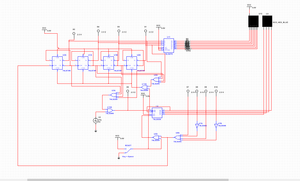

Above you see the same circuit in different forms. The first circuit was built in the regular design mode. The second was built in what is called PLD mode. Although the circuit itself does the same thing in each mode, the build is quite different. In design mode, you have power, switches, seven segment displays, and grounds. On the other hand, in PLD, you have digital highs, lows, interactive digital constants, and clocks. The only way to see the display is by analyzing the probes or uploading it onto a breadboard with the PLD wired up. Another major difference between the two would be the use of pins and connectors in PLD. In order to breadboard a circuit from PLD you have to assign pins to the inputs, outputs, and different components. With this, you can upload the circuit onto a breadboard. Without these pins, you wouldn't know where to connect the wires on the breadboard. All in all, I'd say the PLD mode makes the wiring of a circuit much more easier.
Bill of Materials
Fortunately, I did not have to breadboard for this project due to the fact that I have already uploaded two circuits.
Conclusion
1. SSI- Small Scale Integration- Circuits that use chips containing less then 10 gates.
MSI- Medium Scale Integration- Circuits that use chips containing 10-100 gates.
2. This MSI circuit can only count up, and can only start at zero.
3. The flickering of a display is called ripple effect, which is caused by propagation display.
4. The process of counting to 80 starts with the ones unit display, which is linked to the 74LS93 gate. The switch is flicked on which causes the clock to send it's signal. This causes the 93 gate to count up by 1 starting at zero and resetting after displaying 9. Each time an A is detected, it starts over from zero again. But this also causes the tens display to count up 1 as well. But for the 10s display, which is wired through flip flops, the upper limit is set to 9, but it stops once displaying an 8. So the cycle keeps going 0-9 on the second display with an increase of 1 on the first display, finally stopping when the first displays an 8 and the second displays a 0. The cycle will only reset when the switch is flipped again. This models the change in employees behind the counter after each 80 customer period.
5. The people around me didn't really have circuits different from mine. However, it is very much possible that this circuit be created in a different way.
